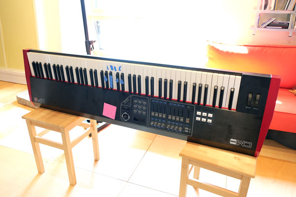
The action of the CME UF8 keyboard controller is among the smoothest and most natural around. When it works. An oft-cited defect of this product (which is no longer made or even supported by its Chinese manufacturer) is the tendency for keys to get stuck in the down position. The only fix is to open up the whole thing, remove every single key, ream out the shaft-hole of each key with a 5/16" drill bit, lubricate each hole, and reassemble everything. It's painstaking (allow yourself an afternoon), but it's neither rocket surgery nor brain science. The results are well worth the effort.
These are notes rather than a comprehensive "how to". The photos were taken during several different partial repair sessions, whereas the written text is about repairing all 88 keys at once. For this reason the photos don't always jive exactly with the corresponding text. But I hope you can read between the lines and the photos to figure out what's what. I hope it's helpful.
Part 1: Releasing the keyboard assembly
This project has several distinct stages: detaching the keyboard assembly from the other electronics that lie just under the front panel; removing the keys from the keyboard assembly; repairing the individual keys; putting everything back together.
You'll be unscrewing many screws at each stage of the disassembly (about 200 screws in all). Before you start, make sure you have somewhere to put them where they won't get all mixed up. About 10 small yogurt containers work for me.
Unplug the UF8 and lay it on its back:
- Before removing any screws from the bottom, please note:
- Leave all 4 rubber feet in place.
- Do not undo the 4 hex bolts.
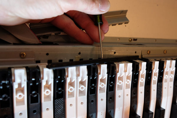
- Two screws should only be loosened (each is held in place on the inside by a hex nut). See photo.
- As you remove a screw, write down next to the screw-hole what kind of screw it is (wood or machine). This makes reassembly much easier.
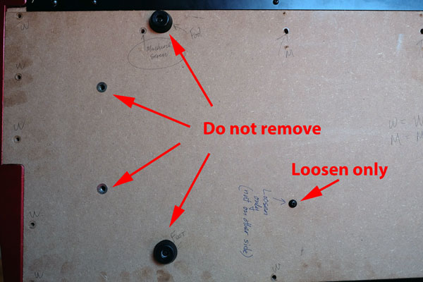
Don't go wild and unscrew everything!
Remove the two remaining screws from the metal front panel. Remove front panel.
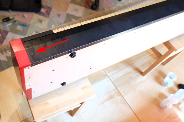
Front panel detail.
Front panel removed.
Tip the keyboard back down flat (its normal position). Remove the top panel gently. Note that there are several cables connecting the front panel to the keyboard assembly. With a marking pen, mark the two big ribbon cables "LEFT" and "RIGHT".
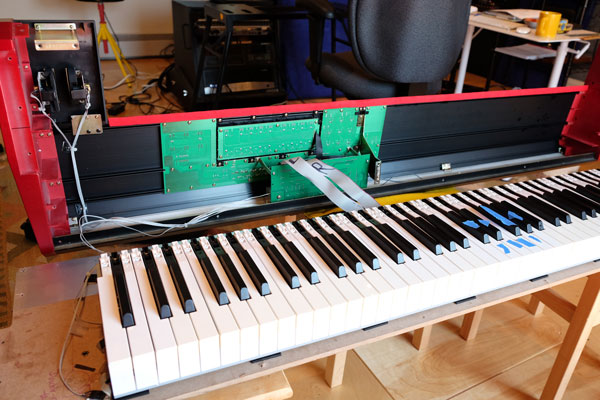
Lift off the front panel carefully! (In this photo, the ribbon cables are already marked from a previous repair).
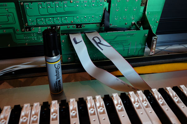
Mark the cables Left and Right.
Gently unplug the two ribbon cables from the circuit board.
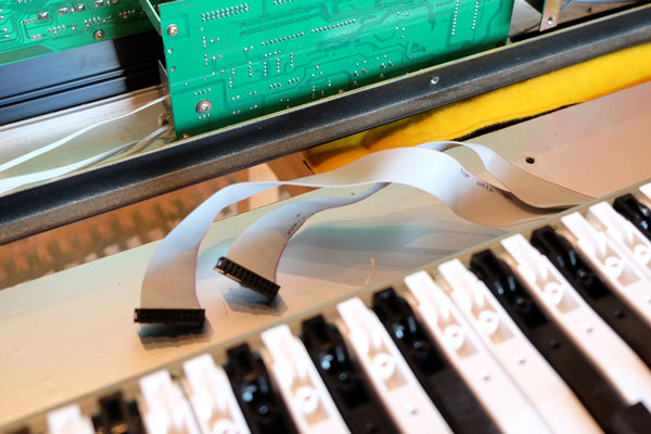
Cables unplugged.
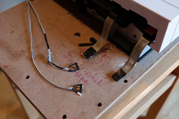
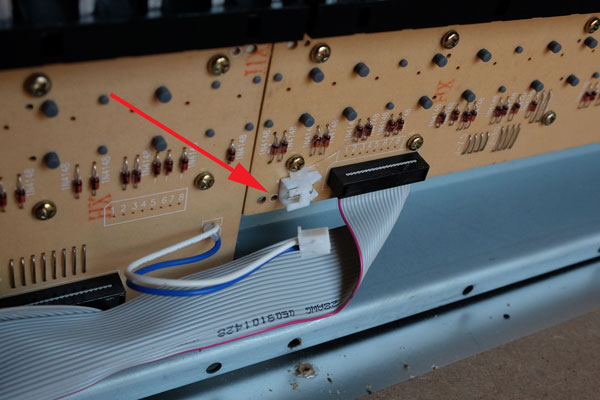
Note the two cables on the left (low) end of the keyboard assembly. Their jacks are attached to the base with double stick tape. With a razor blade, gently peel back the double stick tape (without slicing the cables, obviously!). Now "paint" one of the cable pairs clearly with a marker. Draw a big, fat, black arrow pointing toward its corresponding female jack. Gently unplug both connectors. (For good measure, I tied a loose figure-8 knot in one of the cable pairs.) Don't worry about the polarity of these plugs.
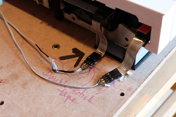
Use a black marker to "paint" one cable and draw a big arrow towards its jack.
Ribbon cables unplugged.
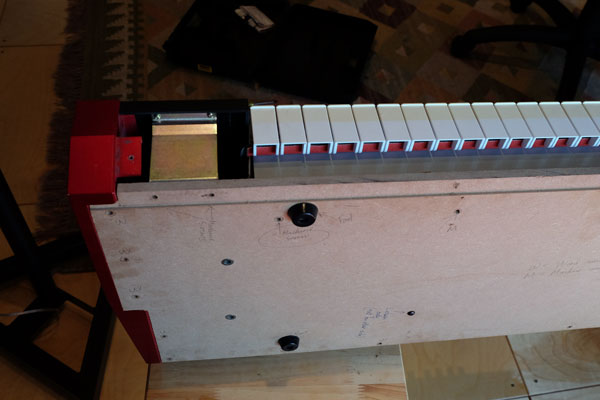
The final step in releasing the keyboard assembly from the wood base involves simply removing the screws from the back flange of the keyboard assembly. Two of the screws are bolts that are retained by nuts (these are the bolts that you loosened way back near step one); the rest are wood screws. Again, as you remove the screws, use a marker to indicate what type of screw came from which hole. Trust me: you'll be glad you did!
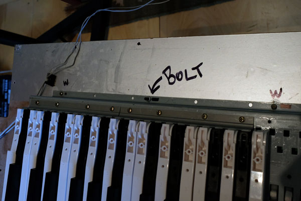
Two machine bolts and several wood screws hold the keyboard assembly to the base board.
The keyboard assembly is now free to move. You can now move it independently of the base, without worrying about tugging on any of the connections to the circuit boards on the top control panel.
Part 2: Removing the individual keys
Note that the keys are grouped in banks of 12 (octaves, conveniently). Remove the four screws that hold the octave retaining clip in place. Remove the metal retaining clip by gently prying it up off the metal frame and siding it out from the back of the keys. Next, gently pry up the plastic pressure clip from the metal frame and remove it.
Just four screws keep an entire octave in place.
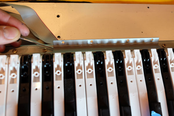
Loosening the octave retaining clip.
Loosening the plastic pressure clip.
IMPORTANT! Before you start wildly yanking out the keys, you need to know that each key contains a tiny — and crucial — spring. If you're not careful, the spring can pop out and go flying across the room. Handle each key gently! When you remove it, keep an eye on the spring, and set it the key down gently on a soft surface, where your dog or cat won't disturb it.
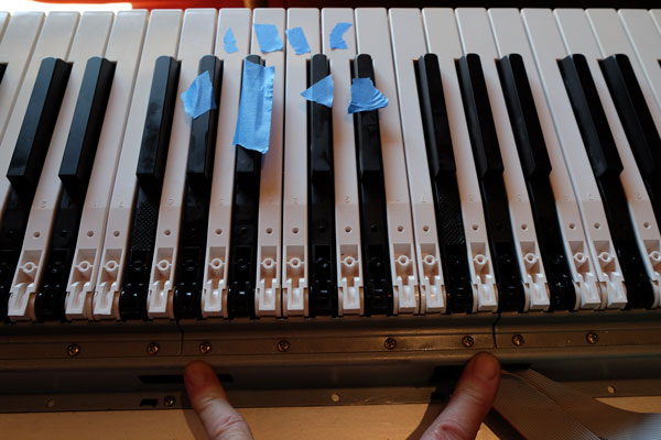
To remove the keys, start with the white keys (the black keys won't come out until their adjacent white keys are removed).
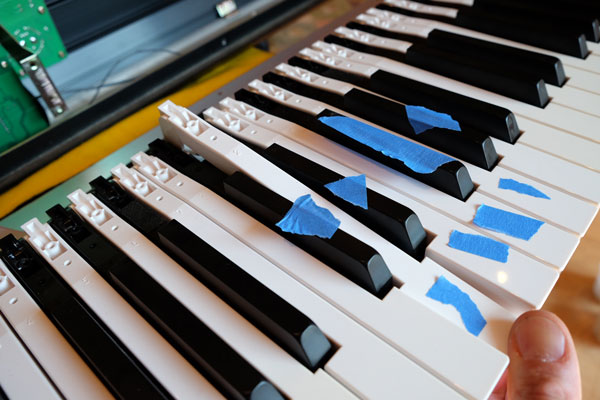
Press down on a white key and slide it to the rear.
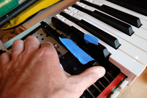
Push the black key towards the rear, then push down. Note that each black key rests on a white plastic-coated post.
As you start removing keys, you'll notice some little plastic "Chiclets" popping off and landing on the floor or disappearing inside the keyboard assembly. Do not panic. Just collect them as you go; they are easily put back in place during reassembly.
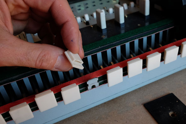
Do not eat these Chiclets.
Unscrew the 16 screws that hold each octave bank. Note: there are three types of screws here (see pic). Be sure to keep the screw types separate as you proceed. (Three separate yogurt containers!)
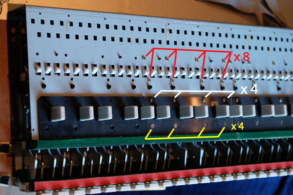
Three sets of screws in each octave bank.
Tap gently on the two small black plastic pins with a screwdriver handle. This should be enough to release the action mechanism. (If not, try also tapping a couple of times on the four large black plastic pins.)
Carefully turn the keyboard assembly over onto its back. Notice that there are two circuit boards, joined by a two-wire cable. Gently pull out the cable plug from its jack.
Unplug this cable.
Unscrew the screws that hold these two boards in place, saving them in a yogurt container. I think there are about 60 of these screws. Remove the two circuit boards and set them down safely away from your work area.
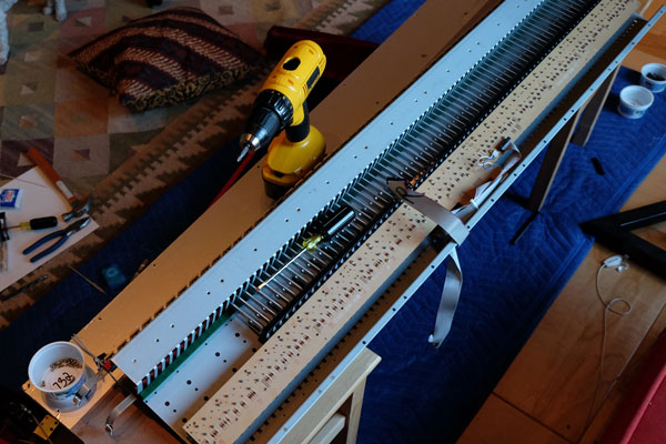
Here's where you'll be glad to use a power driver.
Now you can pull each octave bank's action assembly right out from the frame. (If they resist, try reaching underneath and gently tapping those little black retaining pins again.)
Part 3: Repairing the action
From here on, work on just one octave at a time. If you remove and disassemble all seven octave banks (eight, if you count the tiny four-note one at the top end), you'll wind up with a hopeless pile of parts, with no way to figure out what goes where. One octave at a time!
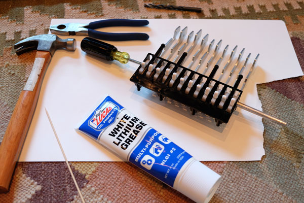
Set the octave bank action assembly on a clean workspace (we don't want to get any crud stuck to the lubricated parts!). Gently tap the aluminum shaft out from one end of the action assembly, using a hammer and screwdriver. Once it's moved a few inches, you can work the shaft out completely with pliers, using a back-and-forth twisting and pulling motion. The weights will drop out of the black plastic housing as the shaft slides out. Be sure to keep track of the order in which they come out. (But don't panic if they get mixed up — you can always use another octave bank as a reference to see what the correct order is. This is why we do one octave at a time!)
Note the little white plastic top-hat attached to the nylon bushings. These have a tendency to come off during handling of the weights. Don't worry. You can put them back on when you're done with the octave bank. For now, just notice that there are two kinds — one for the black keys, one for the white.
You now have 12 key mechanisms to repair.
To fix each key mechanism, run a 5/16" drill bit a couple of times through the hole of the mechanism. Gently does it! Use a very low speed drill so as not to damage anything. You'll end with some dirty and gooey schmutz on the drill bit and at the opening of the hole. Just wipe it off with a clean rag. "Floss" the inside of the hole by poking another clean rag back and forth through the hole. Repeat for all 12 keys (keeping them in order, of course). Sorry, no photos. :(
Now lubricate each hole with a small bead of lithium grease, applied with a toothpick, bamboo barbecue skewer, etc. Just a little dab is all you need. Spread it around the inner surface of the hole. Repeat for all 12 keys (keeping them in order, of course). Sorry, no photos. :(
Wipe the axle/shaft clean with a clean rag.
Reassemble the octave bank. (Use another one as guide to show you what's what.) Make sure all the white plastic top-hats are accounted for and correctly seated on their keys.
With the octave bank back together, make sure the weights all move freely about the shaft. Each key should flop easily up and down as you move the assembly around in your hands and poke the weights. If there is any hesitation or stickiness in any one of the keys, you must take the octave bank apart again and fix it. Now is your only chance to fix it.
Repeat for each octave bank.
Part 4: Reassembly
You now have seven (and one-third) nicely lubricated and freely moving octave banks. You're almost done!
Before reassembling, set your power driver to the lowest torque setting. You do not want to strip any of these small screws.
The strategy is simple: follow the disassembly instructions in reverse. Here's an outline:
- Insert each octave bank into its corresponding position in the base. Press each one in place firmly but gently, so that the black plastic pins engage in their respective holes and snap into place. As you're doing this, make sure that the top-hats don't fall off and get lost. If one comes off, stop and put it back on (you can hold it in place by putting a tiny bead of grease under it).
- Replace the two circuit boards, with their 60-odd screws. Reattach the cable that joins the two boards.
- Flip the keyboard over and proceed octave-by-octave to replace the 16 retaining screws in each octave.
- Test the action of each key. If you discover that any of them are sticky, you'll just have to go back and fix them. (Do this now, before proceeding any further!)
- Replace the plastic keys: black ones first, then the whites. Handle the keys gently: don't lose those tiny springs! Make sure that each key has its white plastic Chiclet in place.
- Octave by octave: replace the plastic pressure clip. You may have to tap some keys gently with a screwdriver to get them to slide forward far enough for the clip to engage.
- Octave by octave: replace the metal octave retaining clip and secure its four screws.
- Reattach the keyboard to the base (two machine bolts and several wood screws).
- Reattach the two ribbon cables on the left (low) end of the keyboard. Use a drop of glue (glue gun) or a bit of double-stick tape to secure the jacks back in place on the base.
- Reattach the Left and Right ribbon cables to the top control panel.
- Lower the top control panel onto the keyboard. Make sure the cables are all free and don't get pinched between the top and the base.
- Tip the machine onto its back edge.
- Reattach front panel.
- Reattach base.
- Test everything.
- Celebrate.
- Make beautiful music.
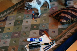
Keep your assistant out of your hair by giving him a carrot.